一、Purpose
Through the example of measuring the height and width of object surface features in Capture contour mode using Next vision tech 3D camera, you can quickly master the use of Yisight 3D camera and verify the accuracy of camera measurements. As shown in Figure 1, this is a standard test workpiece for processing, and the test guide demonstrates measurement by measuring the height of 0.1mm and width of 3mm of the sawtooth indicated by the measurement arrow.

Figure 1. Test piece
二、Camera connection
1、Hardware connection
Ensure that the camera is powered on properly and that the indicator lights are working properly as shown below:
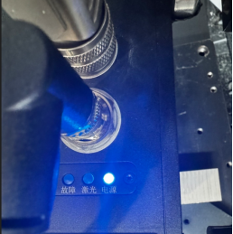
Figure 2, camera powered on
As shown in the figure above, the power indicator light is normally on, that is, the camera is successfully powered on. At the same time, the camera is connected to the host where the Capture software is located, and the network segment of the host computer and the camera are set in the same network segment.
2、Software connectivity
Open Capture for automatic search, connect camera, as shown in the figure below:

Figure 3. Camera search connection
As shown in the figure above, step 1, 2 and 3 are carried out. If the camera is not found, please check whether the camera is powered on and the network cable is normally connected; if the camera can be found but cannot be double-clicked, check whether the host network segment and the camera network segment are set differently.
After the connection is successful, click the photo button in the figure below to obtain the laser line map in real time. If the laser line of the measured object can be seen normally, the camera connection is successful.

Figure 4. Collection button
三、Test steps
1、Parameter setting for acquisition
Accurate measurement accuracy cannot be separated from good imaging, before measurement, exposure and other parameters need to be adjusted for the object to be measured;
Among them, the parameters are adjusted, including exposure time, gain, laser power, exposure mode, etc., so as to make the laser line map reach the best score on the object under test, and at the same time not lose points.
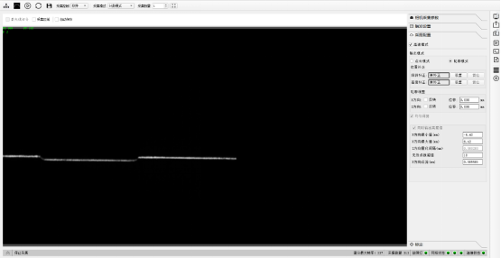
Figure 5, parameter adjustment
2、Tilt correction
Due to the camera installation and the placement of objects, the tilt occurs, so it is necessary to correct the tilt and subtract the influence of external factors.
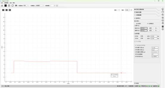
Figure 6, correction steps
After following the steps 1, 2, 3 and 4 in the above figure, the interface for setting the correction area for inclination will appear as shown in the figure below:
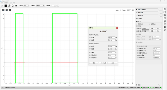
Figure 7, calculation of tilt correction parameters
After the above steps 1, 2 and 3, the inclination correction is completed, and the width and height can be measured at this time.
3、measurement of elevation
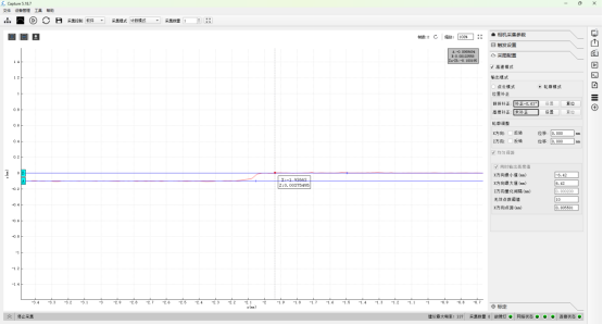
Figure 8. Height measurement
As shown in the figure above, click the button at 1 to draw two height lines. By adjusting the two lines to the upper and lower surfaces of the object under test, you can zoom in or out with the mouse to make the selection more accurate. The result is shown in Figure 2 above, which is 0.100195mm.
4、Measurement of width
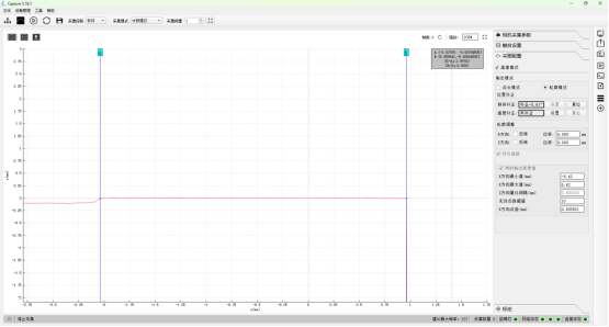
Figure 9, width measurement
As shown in the figure above, by clicking button 1, the X-axis width and height measurement can be performed, adjusting the two position lines AB as much as possible to align with the left and right boundaries, the measurement result is shown in Figure 2 above: .99703mm, it is important to note that unlike the measured height, here the focus should be on the value of Xb-Xa.
四、sum up
Through the above examples, the width and height information of the object surface can be measured simply and quickly through Capture software, and the measurement accuracy of the hand Yishixing camera can be rapidly verified;
This mainly includes several steps, mainly: camera connection, parameter adjustment, tilt correction, measurement. At the same time, the problems encountered in the process of camera connection are also explained, which can better help you to use the camera quickly.
 2024/11/15
