I. Purpose
By reading this guide, you can quickly obtain 3D contour data of object surfaces, perform contour measurement and point cloud related intelligent analysis using Next vision tech Capture software.
This guide mainly demonstrates the contour point cloud data collection and generation through the standard prism test piece in the following figure for users to use as a reference.

Figure 1, test piece
2. System connection
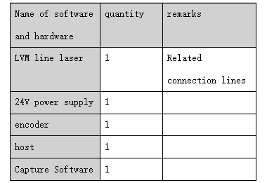
The software and hardware required for this section are shown in the table below:
Table 1: List of software and hardware
1、Hardware connection
This section mainly explains camera connection, encoder connection and software connection.
A. Camera connection
Ensure that the camera is powered on properly and that the indicator lights are working properly, as shown below:
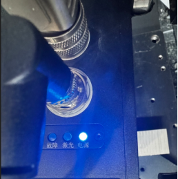
Figure 2. Power on the camera
As shown in the figure above, the power indicator light lights up normally, that is, the camera is powered on successfully. At the same time, connect one end of the camera to the host where the Capture software is located, and set the network segment of the host computer and the camera in the same network segment.
B. Encoder connection
Hardware connection of the encoder, this part needs to understand the specific representation of each line of the LVM line laser, as shown in the figure below:
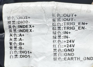
Figure 3, meaning of LVM line laser beam
The four wires in the figure above (A+), gray (A-), purple (B+), and purple black (B-) need to be connected to the encoder. The corresponding wiring on the encoder is as follows:

Figure 4, Encoder and camera connection wiring diagram
As shown in the figure above, the wiring of the LVM line laser A/B line corresponding to the encoder is shown in the figure above. C. Software connection Open Capture for automatic search and connect the camera as shown in the figure below:

Figure 5. Camera search connection
As shown in the figure above, step 1, 2 and 3 are carried out.
If the camera is not found, please check whether the camera is powered on and the network cable is normally connected; if the camera can be searched but cannot be connected by double clicking, check whether the host network segment and the camera network segment are set differently.
After the connection is successful, click the photo button in the figure below to obtain the laser line map in real time. If the laser line of the measured object can be seen normally, the camera connection is successful.

Figure 6. Collection button
3. Test steps
1. Connect the hardware and software according to the chapter "II. System Connection";
2. Parameter setting for data collection
Accurate measurement accuracy cannot be achieved without good imaging before measurement parameters such as exposure need to be adjusted for the object being measured; among these adjustments parameters including exposure time gain laser power exposure mode etc. are adjusted to ultimately achieve a laser line map score of over 90 points on the object being measured while ensuring no point loss etc.
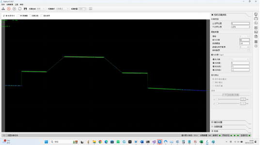
Figure 7, parameter adjustment
3. Point cloud data acquisition The software related settings are as follows:

Figure 8, Encoder Settings
As shown in the figure above, the following will be explained from 1 to 4 respectively:
<1> Select the software for acquisition control, acquisition mode and counting mode. The number of acquisition (this can be filled with an initial value according to the actual length of the object. If the number of scan lines is not enough, you can increase it). <2> Trigger source selection: Encoder
<3> Encoder resolution mm: Note that this value is the actual resolution of the encoder grating ruler (the encoder grating ruler resolution in this article is 0.002mm, that is, the minimum distance of movement that can be distinguished each time is 2um). Users can fill in their own encoder grating ruler resolution;
<4> Triggering the division ratio, which is understood as the number of pulses counted by the encoder (moved by M 2um) triggering one LVM line laser to capture a contour;
<5> Trigger interval mm: automatically calculated (here represents the interval between two contours in the point cloud);
<6> Maximum frame rate
In particular, if the trigger frequency ratio is filled with unreasonable information, it may lead to incomplete sampling, as shown in the following figure:
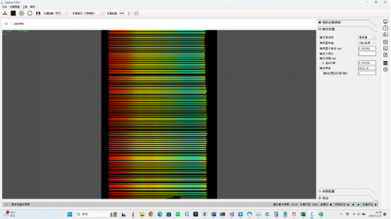
Figure 9, partial outline lost
As shown in the figure above, at this point the trigger divide ratio is 1, and the middle black line indicates that the contour data is lost. We can achieve complete data acquisition by adjusting the encoders moving speed, modifying the trigger divide ratio, or increasing the frame rate by reducing the image ROI. This guide mainly explains how to achieve complete data acquisition by modifying the trigger divide ratio as follows:
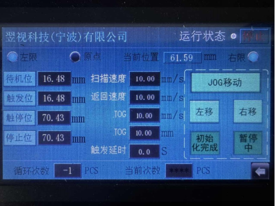
Figure 10, Encoder parameters
As can be seen from the above figure, the encoders moving speed is 10 mm/s, denoted by S, and the encoder resolution is 0.002 mm. According to item 6 in Figure 6, the maximum frame rate of LVM line laser under this setting is 2518 Hz, denoted by F; at this time, the 1s clock encoder can trigger N pulses:
N = S/0.002 * 1; that is, N=5000 formula-1
It is known that when the trigger frequency ratio is 1, N> F (2518), which means that the speed at which LVM captures contours is lower than the trigger speed. Clearly, the encoder triggers too quickly, causing the LVM line laser to fail to capture contours in time, resulting in data loss; as mentioned above, the trigger frequency ratio can enable the encoder to trigger M pulses before the LVM line laser captures contour data. Therefore, as long as:
* Trigger the ratio of the divider to N (5000) is sufficient
The trigger frequency ratio should not be set too large, which will lead to the data contour of the object surface being too sparse. In this paper, the trigger frequency ratio is set to 4 to fully collect the surface contour data of the object, as shown in the following figure:
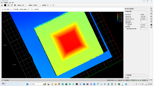
Figure 11, object contour point cloud data
IV. Summary
In the above example, object contour scanning can be performed simply and quickly through Capture software to obtain 3D point cloud data. This technical guide describes in detail the connection of LVM line laser hardware and software to contour point cloud data acquisition.
Note: In order to obtain the complete surface profile data of the object, it is necessary to pay attention to the important information such as the encoder moving speed, encoder resolution, encoder division ratio, and maximum frame rate.
 2024/12/13
