 2025/02/17
Background knowledge
In the manufacturing process of modern smartphones, the mobile phone shield cover is a crucial component for ensuring stable mobile phone signals and the normal operation of electronic components. Therefore, quality control of the shield cover is of great significance. The step difference, as one of the important indicators for measuring the quality of mobile phone shield covers, requires precise detection. Industrial 3D cameras play an indispensable role in the field of detecting the step difference of mobile phone shield covers with their unique technical advantages.

Camera Selection
Today, we will introduce a successful application case of the LVM2050 line laser 3D camera developed by Yishi Technology in the 3C industry!
The LVM2050 3D intelligent sensor has a full - frame acquisition rate of 340Hz, and can reach up to 10000Hz by setting the Region of Interest (ROI). It has 2048 physical contour points and can reach up to 4096 points under the condition of uniform interval sampling of depth maps. It meets the requirements of various high - speed and high - volume detection applications and is a cost - effective 3D intelligent sensor!

Detection Items

Workpiece Information
· Material: Metal, PCB board
· Color: Silver, black, green
· Size: 220*250mm
Detection Requirements
· Detect the step difference from each metal surface to the PCB board.
· Conduct an overall planar scan.
· Achieve an accuracy of 0.05mm.
Detection Environment and Installation Method
· Scanning Method: The camera is fixed, and the test sample moves along the central straight line for scanning and measurement.
· Triggering Method: An encoder is used for triggering, outputting stable AB - phase differential signals.
· Communication Method: TCP/IP Ethernet.
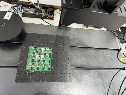
The figure shows the installation diagram of the camera. For the actual installation, please refer to the structural design.
Image Acquisition Effect

The figure shows the point cloud map of the physical object.
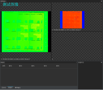
The figure shows the test image processed by the algorithm.
·Detection of small-sized samples

The figure shows the position of the repeatability data for small-sized samples.
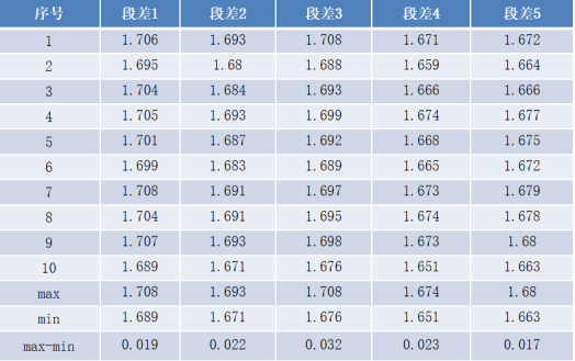
The figure shows the repeatability data of Material No.1 for small-sized samples.
The figure shows the repeatability data of Material No.2 for small-sized samples.

The figure shows the repeatability data of Material No.3 for small-sized samples.
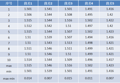
· Detection of large-sized samples
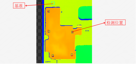
The figure shows the position of the repeatability data for large - sized samples.

The figure shows the repeatability data of large-sized samples.
Detection Conclusion
When using the LVM2050 camera, its field of view can cover the entire PCB board during scanning. The camera is installed horizontally for scanning, and both the metal materials and the PCB board are clearly imaged. The maximum step - difference repeatability data is 0.032mm, which meets the customer's accuracy requirement of 0.05mm.

