 2025/11/28
Background knowledge
In the reflow soldering process of military manufacturing, the SMT through-pass carrier acts as a 'hidden skeleton' —a precision board—to support circuit boards and prevent deformation. The height tolerance and flatness error of the carrier directly determine the yield of component soldering, while its accuracy is closely related to the equipment's vibration resistance and thermal stability.
Traditional manual inspection methods are inefficient and prone to errors, as 2D vision can only detect "planar projections." The advent of 3D industrial cameras, however, has revolutionized the field by achieving micron-level.

precision, establishing them as the "digital gatekeepers" of carrier quality. By transitioning from human-based experience to precise 3D data quantification, industrial cameras are transforming the inspection of SMT soldering carriers from qualitative to quantitative.
Camera Selection
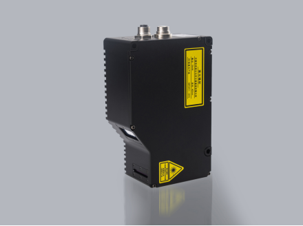
Today, we're showcasing the military applications of Next Vision Tech's LVM2520 linear laser 3D camera!
The LVM2520 3D intelligent sensor features a full-frame acquisition rate of 2500Hz, with an adjustable ROI setting up to 56000Hz and a repeatability accuracy of 0.4μm. Ideal for 3D inspection of micro components, it is the perfect choice for high-speed online inspection systems.
surveillance project
·Check the flatness and height of the workpiece
·Product dimensions: Maximum 400×400×20mm; test product 240×200mm
·Repeatability requirements: The repeatability of boss height, groove depth, and flatness must be 0.01mm, while the repeatability of locating post height must be 0.004mm.
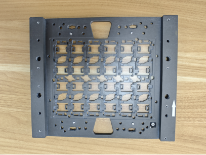
*Product image
Check the environment and installation method.
·Scanning method: The camera is fixed, and the test sample is scanned along a central straight line.
·Triggering method: Encoders trigger to output stable AB phase difference signals
·Communication mode: TCP/IP Ethernet
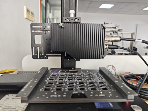
Image capture effect

*The image shows a depth map
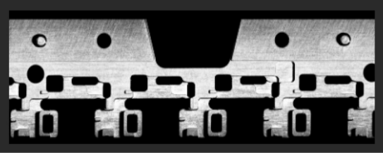
*The image shows a brightness map
measured data
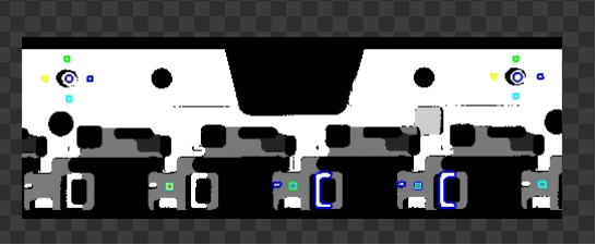
·Depth image based on camera acquisition
·The product is tested using tools such as preprocessing, spot analysis, and height detection
·Use two positioning pillars as reference to calculate the boss height and groove depth (average value)
· Calculate the average height of the positioning column using its perimeter as the reference
DA
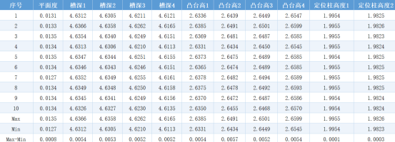
*Data description: 10 static measurements show the flatness repeatability is 0.0008mm, the groove depth repeatability is 0.0054mm, the boss height repeatability is 0.0057mm, and the locating post height repeatability is 0.0003mm.
Test conclusion
·This solution provides good imaging results. The testing environment is limited, and only partial images are captured.
·Repeatability: After 10 static measurements, the flatness repeatability is 0.0008mm, groove depth repeatability 0.0054mm, boss height repeatability 0.0057mm, and locating post height repeatability 0.0003mm, all meeting the testing requirements.
·Speed: Maximum frame rate of 6800Hz (depth of field compressed to 7.5mm), theoretical maximum speed of 108mm/s (XY ratio: 1:1, XY pixel pitch: 0.016mm)

